2 KW Servo Motor Drilling Infeed CNC H-Beam Drilling Shearing And Tapping Machine Line 500×500mm Size
Machine tool use:
This machine tool is primarily dedicated to drilling, tapping, and marking processes for steel materials like H-shaped steel and channel steel. It leverages three BT40 high-speed spindles to execute drilling on the three surfaces of the steel, with one spindle designated for each surface. The corresponding row-type tool magazine is able to house up to 4 specifications of drill bits.
It is distinguished by high processing efficiency, high precision, convenient operation, and extensive applicability. It is widely employed in steel structure industries such as construction, garages, towers, and grids.
Specifications:
| H beam parameter |
Max. Size Width x Height |
500×500mm |
| Min. Size Width x Height |
100×100mm |
| Beam Length |
2000~13000mm |
| |
Channel steel |
10#~40# |
| Main spindle |
Qty. |
3 |
| Model |
BT40 |
| Motor power |
11 kW |
| Spindle speed |
100~3000 r/min |
| Hole diameter |
φ5~φ30 mm |
| CNC axis |
Servo motor power of X axis |
About 4.5 kW |
| Servo motor power of horizontal drilling positioning axis |
About 1.5 kW |
| Servo motor power of vertical drilling positioning axis |
About 3 kW |
| Servo motor of drilling infeeding |
About 2 kW |
| Tool magazine |
Qty. |
3 |
| Type |
Row style |
| Tool magazine capacity |
4 x 3 |
| Processing Accuracy |
Hole distance deviation |
Two holes within 1 meter |
±0.5 |
| The allowable deviation value increases by ±0.2mm for every additional 1 meter of the hole distance, and the maximum does not exceed ±2mm |
| End margin deviation |
±1.0 mm |

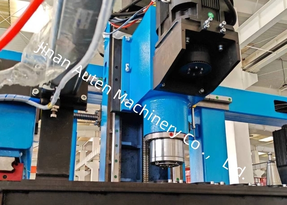
1. Drilling Machine
The drilling machine is primarily composed of a base, a bed, a movable slide, a spindle box, an upper pressing device, a side clamping device, and a row tool magazine.
The machine tool is equipped with three spindle boxes: the fixed side spindle box, the movable side spindle box, and the upper unit spindle box, which are respectively utilized for drilling operations in horizontal and vertical directions. Each spindle box can operate independently and perform drilling simultaneously, significantly enhancing production efficiency. Each spindle box is furnished with a set of BT40 high-speed mechanical spindles, and the corresponding row tool magazine can accommodate a maximum of 4 drill bits with different diameters (when no tool is mounted on the spindle). It enables automatic processing of 4 different hole diameters in a single workpiece clamping. The spindle feed is driven by a servo motor, allowing for fast forward, working feed, and fast backward movements via program control; the spindle motor is powered by a spindle servo motor, featuring stepless speed adjustment with a wide speed regulation range.
The three spindle box units are mounted on the side of the bed. Each spindle box unit is driven by two sets of servo motors to realize horizontal and vertical movement, with transmission via ball screws and guidance by precision linear rolling guides. During the drilling process, this equipment presses the workpiece in two directions: a hydraulic cylinder drives a pressing mechanism above the workpiece to press it against the horizontal support roller, while another hydraulic cylinder drives a side pressing mechanism to clamp the workpiece from the side.
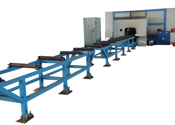
2. Feeding Channel
The feeding channel is composed of a channel bracket, support rollers, side positioning rollers, side pushing mechanisms, racks, and other components. It is designed to carry workpieces to be processed. A photoelectric switch is installed at the front end of the channel to detect the front end of the workpiece and determine the X-direction processing reference. The side positioning rollers perform rough positioning of the workpiece in the Y direction, while the side pushing mechanisms press the workpiece against the side positioning rollers.

 Your message must be between 20-3,000 characters!