Model BHD1250C CNC H Beam Drilling Sawing And Shearing Machine Line BT40 Main Spindle
Product Introduction:
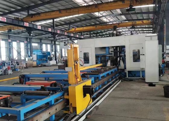
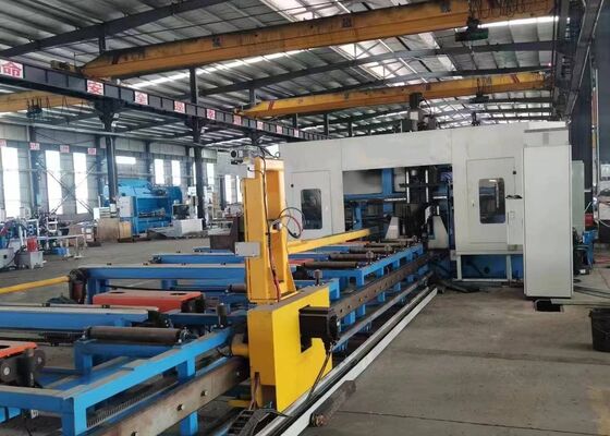
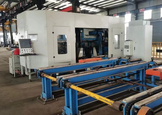
This CNC Beam Drilling Line is specially engineered for high-precision drilling applications on H-beam structural components. Equipped with three high-speed precision spindle units, the machine delivers efficient multi-directional drilling performance with excellent machining accuracy and operational convenience. As a reliable and advanced processing solution for the steel fabrication industry, it is extensively applied in various fields, including construction steel structures, bridge engineering, transmission tower manufacturing, and large-scale grid structure projects.
Product configuration information:
| H beam parameter |
Max. Size Width x Height |
1250x600mm |
| Min. Size Width x Height |
200×75mm |
| Max. Beam Length |
12000mm |
| Main spindle |
Qty. |
3 |
| Model |
BT40 |
| Motor power |
3x11 kW |
| Spindle speed |
200~3000 r/min |
| Max. Hole diameter |
φ40 mm |
| Motor power |
Feed servo motor power |
2x3 kW |
| Positioning servo motor power |
2x3 kW |
| Processing Accuracy |
Hole distance deviation |
Two holes within 1 meter |
±0.5 |
| The allowable deviation value increases by ±0.2mm for every additional 1 meter of the hole distance, and the maximum does not exceed ±2mm |
| End margin deviation |
±1.0 mm |
| Hydraulic system |
Hydraulic pump pressure |
7 MPa |
| Oil pump motor power |
7kW |
| Electrical System |
Control method |
PLC |
| Number of CNC axes |
7 |
| Overall size (L x W x H) |
32000x6200x4000 |

Product Features
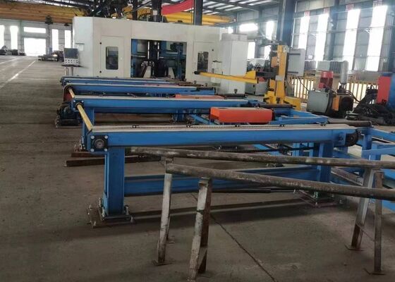
1. The 3D CNC H-beam drilling and cutting machine comprises a heavy-duty machine frame, CNC feeding system, material handling system, electrical control system, hydraulic system, cooling system, lubrication system, scrap collection unit, and other auxiliary assemblies. Designed with a fixed machine bed and movable workpiece configuration, the equipment is specifically engineered for the machining of large-size H-beams. It enables continuous automated production while delivering high processing efficiency, reliable operational stability, and consistent machining performance.
2. The machine structure consists of the main machine bed, CNC sliding table assemblies, support mechanisms, upper clamping units, side clamping units, and workpiece detection systems. The CNC sliding assemblies comprise fixed-side slides, movable-side slides, and upper spindle sliding units. Specifically developed for H-beam processing, each sliding assembly incorporates a sliding plate, slide base, spindle headstock, high-speed mechanical spindle, tool cylinder, variable-frequency motor, servo motor, linear guideways, and precision lead screws, providing accurate positioning, smooth movement, and stable machining performance.
3. The CNC feeding system consists of support brackets, rack-and-pinion transmission mechanisms, servo motors, reducers, and feeding manipulators. Powered by the servo motor, the feeding manipulator precisely conveys H-beam workpieces along the X-axis, ensuring accurate feeding control, stable material positioning, and reliable workpiece transfer throughout the machining operation.
4. The material handling system incorporates both an in-feed conveyor and an out-feed conveyor. The in-feed conveyor is composed of conveyor support structures, supporting rollers, and lateral positioning mechanisms, which facilitate the transportation of steel profiles, accurate Y-axis positioning, and coordinated material loading with the CNC feeding system, thereby ensuring efficient and stable workpiece feeding. The out-feed conveyor consists of discharge supports and roller assemblies, enabling smooth and reliable transportation of finished workpieces following the machining process.
5. The cooling system utilizes a combination of internal and external cooling methods together with oil mist lubrication technology to effectively control heat generated during drilling operations. This optimized cooling solution reduces coolant consumption, lowers overall production costs, supports cleaner and more environmentally responsible manufacturing, and prolongs drill tool service life by minimizing thermal wear and heat-related tool degradation.
6. The hydraulic system provides dependable hydraulic power for the upper clamping mechanism, side clamping mechanism, tool cylinders, and other hydraulically actuated components. It ensures secure and stable workpiece clamping while maintaining reliable machine operation throughout the machining cycle.
7. The pneumatic system provides compressed-air power for the feeding manipulator, detection cylinders, and other pneumatically operated components. It ensures rapid actuation, responsive control, and reliable automated operation of the relevant machine mechanisms.
8. The lubrication system combines centralized automatic lubrication with manual lubrication methods. The centralized lubrication system delivers timely and accurately metered lubrication to critical moving components, including linear guideways and precision lead screw assemblies, effectively minimizing mechanical friction and wear while maintaining long-term machining precision and equipment reliability.
9. The machine control system integrates an industrial computer, PLC controller, and associated control components to achieve intelligent and automated machine operation. Processing programs can be generated by importing CAD drawings or entering machining parameters through USB interfaces or keyboard input. The system allows machining programs to be stored, recalled, displayed, and transferred according to designated part numbers whenever required. It also permits individual machining parameters to be manually adjusted while supporting fully automatic execution of the complete production cycle, substantially enhancing operational flexibility, production efficiency, and overall manufacturing productivity.
During sample demonstration sessions, the CNC beam and sheet metal drilling, marking, and shearing machine effectively showcases its processing capabilities using standard H-beam specimens with different flange widths and web thicknesses, together with channel steel samples in various dimensions. The demonstrated workpieces clearly illustrate the machine's capability to achieve accurate hole positioning, clean and precise tapped threads, and clearly defined marking patterns, providing a comprehensive demonstration of its excellent machining accuracy, process consistency, and operational reliability in practical industrial applications.
The High-Speed CNC H-Beam Drilling, Marking, and Shearing Machine is primarily utilized in steel structure manufacturing facilities and bridge construction projects. In steel structure workshops, it ensures precise machining of H-beams used in frameworks and support structures, providing a strong foundation for the stable assembly of steel constructions. In bridge construction, the equipment performs high-precision drilling operations on H-beams, improving the structural integrity of bridges and enabling them to effectively withstand long-term loads. With its exceptional operational efficiency, this machine offers reliable support for these essential infrastructure sectors, contributing to the smooth progress of related projects.


 Your message must be between 20-3,000 characters!