80m/Min Max Feeding Speed CNC Punching Cutting Machine For Angle Steel Industry
Product Introduction:
This equipment combines punching, typing, and shearing functions for angle steel, channel steel, and plates. With a single machine, three distinct operations can be performed on these three types of metal materials.
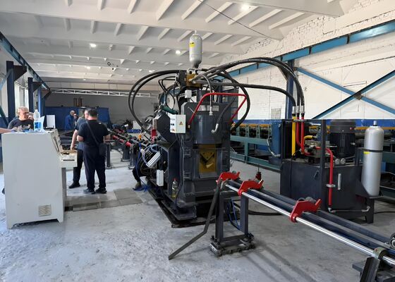
Machine structure:
This production line consists of six components: the workpiece loading section, feeding section, main machine, finished workpiece unloading section, electrical control system, and hydraulic power unit.
Product Parameters:
| Model |
JNC2020 |
| Angle size (mm) |
50х50х4~200х200х20 |
| Max. Punching (Dia. х Thi.) (mm) |
Φ26х20 |
| Punching force (kN) |
1000/1200 |
| Marking force (kN) |
1000/1200 |
| Cutting force (kN) |
2200/4300 |
| Max. length of blank (m) |
14 |
| Max. length of finished (m) |
12 |
| Punches per side |
3 |
| Group of marking letters |
4 |
| Number of letters per group |
18 |
| Character size(mm) |
14x10x19 |
| CNC axes |
3 |
| Cutting mode |
Double Blade or Single Blade |
| Cooling method |
Water cooling/Air cooling/Oil chiller |
| Max. feeding speed (m/min) |
80 |
| Programming mode |
Lofting software or instruction programming |
| Overall dimension (m) |
About 32x7x3 |
| The above parameters can be adjusted and changed according to customer's specific requirements. |

Feature and consist parts:
1. Feeding Section
The feeding section is comprised of a feeding channel and a CNC feeding cart.
Feeding Channel: This includes a conveyor roller, support brackets, a frame, precision linear guideways, and lateral positioning wheels.
CNC Feeding Cart: This consists of a servo motor, drive gear, synchronization belt, cart frame, clamping rod, and clamping jaws.
The workpiece is initially manually placed into the clamp, and the feeding clamp is then automatically advanced by the servo motor to the main machine for punching and shearing, in accordance with the instructions provided by the control system.
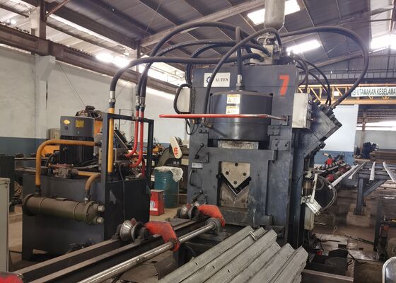
2. Main Machine
This component is comprised of a pressing unit, typing unit, supporting unit, side punching unit, and shearing unit.
Pressing Unit: This is designed to secure the workpiece, prevent any deviation, and counteract the forces generated during punching and shearing.
Typing Unit: It includes a fixed machine base, an oil cylinder that moves the base, a hydraulic power head cylinder, a four-position cylinder that facilitates the transposition of four character boxes, and a manual adjustment mechanism.
Supporting Unit: During material feeding, the support unit is positioned higher than the punching and typing units to prevent the angle steel from striking the lower blade. When punching, the support unit lowers to ensure the quality of typing, punching, and shearing.
Punching Unit: This unit features three punching positions on each side. Each position can be equipped with punching heads of varying diameters according to customer specifications. The punching positioning is driven by a servo motor through a ball screw and square rail, ensuring high precision in positioning.
Shearing Unit: This unit is comprised of a frame, hydraulic power cylinder, upper knife box, lower knife box, translation mechanism, pressing components, and material handling system. The machine is capable of cutting angle steel, channel steel, and plates by replacing the cutting dies with different configurations.
The feeding system is designed to prevent the angle steel from coming into contact with the lower blade. The cutting of three distinct profiles is possible by changing the respective molds.
3. Finished Workpiece Unloading Unit
This unit consists of a workpiece support roller and support shaft.
By pressing the button, the workpiece can be ejected to either the left or right side, depending on the customer’s requirements.
4. Hydraulic Power Section
This machine utilizes a standalone hydraulic station, offering ease of maintenance. The pipe connections are made using ferrule-type fittings, effectively eliminating the risk of joint leakage. The hydraulic valves are integrated through a valve block, utilizing both plate valves and cartridge valves simultaneously. The piping is compactly arranged, ensuring a more efficient hydraulic system with minimized pipeline losses, thereby optimizing overall system performance.
5. Electrical Control
The machine’s electrical control system is both advanced and logically designed, with a user-friendly programming interface that is easy to learn and operate. The control software continuously monitors the machine’s operation. In the event of a malfunction, the CRT screen provides detailed information on the fault cause and offers guidance on corrective actions.
These specimens, representing the standard specifications and typical processing conditions prevalent in the angle steel tower industry, allow users to directly assess the equipment’s quality, precision, and workmanship. They act as a concrete reference for evaluating the equipment’s performance and its compliance with established production standards, thereby enabling informed, data-backed decisions for future applications.
In the construction of ultra-high voltage (UHV) transmission lines—where towers must endure extreme weather conditions and heavy loads—this equipment is crucial for processing the angle steel components that constitute the tower’s primary framework. It reliably performs drilling and stamping operations on the angle steel used for tower bodies, cross-arms, and other critical structural elements, ensuring accurate dimensions and secure connections that uphold the towers' overall stability.

 Your message must be between 20-3,000 characters!