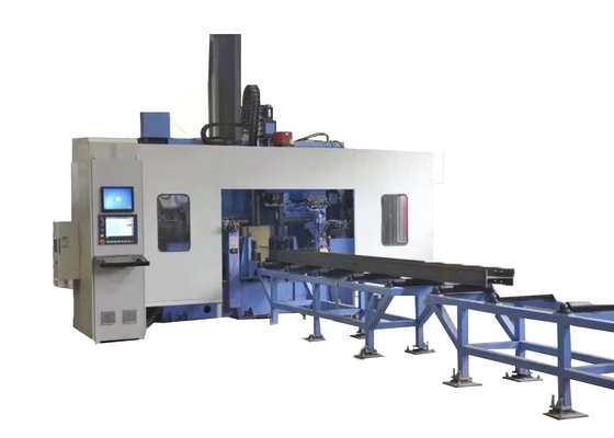
5-30 MM Hole Diameters CNC Beam Drilling Tapping And Marking Machine Line 4 X 3 Row Style Tool Magazine
Machine tool use:
This machine tool is primarily designed for drilling, tapping, and marking operations on steel materials such as H-shaped steel and channel steel. It utilizes three BT40 high-speed spindles to perform drilling on the three surfaces of the steel, with one spindle allocated to each surface. The corresponding row-type tool magazine can accommodate up to 4 specifications of drill bits.
It features high processing efficiency, high precision, user-friendly operation, and wide applicability. It is widely utilized in steel structure industries including construction, garages, towers, and grids.

Machine tool structure and configuration:
This machine tool is primarily composed of components such as a drilling machine, feeding trolley, feeding channel, discharging channel, cooling system, hydraulic system, pneumatic system, lubrication system, and electrical system.
The machine tool adopts a fixed bed and a movable workpiece structure. The three-dimensional drilling equipment with this structure facilitates automated production.
1. Feeding trolley
The feeding trolley is composed of gears, servo motors and manipulators. The manipulator clamps the workpiece and is driven by a servo motor. Under the transmission of the gear rack, the workpiece is fed in the X direction to ensure the longitudinal processing accuracy of the drilling.
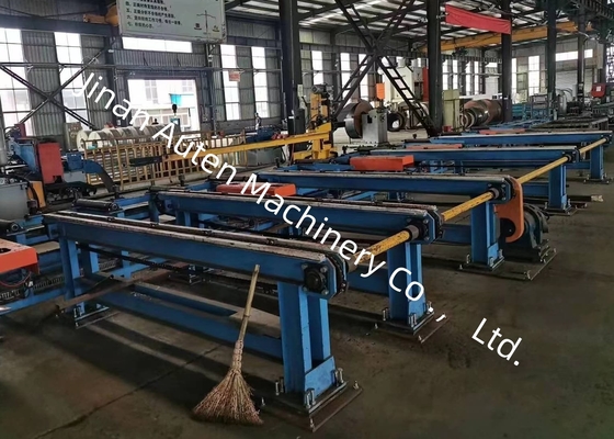
2. Feeding channel
The feeding channel is composed of a channel bracket, support rollers, side positioning rollers, side push mechanisms, racks, etc. The feeding channel is used to carry the workpiece to be processed. A photoelectric switch is installed at the front end of the channel to detect the front end of the workpiece and determine the processing reference in the X direction. The side positioning roller performs rough positioning of the workpiece in the Y direction, and the side push mechanism presses the workpiece against the side positioning roller.
Specifications:
| H beam parameter |
Max. Size Width x Height |
500×500mm |
| Min. Size Width x Height |
100×100mm |
| Beam Length |
2000~13000mm |
| |
Channel steel |
10#~40# |
| Main spindle |
Qty. |
3 |
| Model |
BT40 |
| Motor power |
11 kW |
| Spindle speed |
100~3000 r/min |
| Hole diameter |
φ5~φ30 mm |
| CNC axis |
Servo motor power of X axis |
About 4.5 kW |
| Servo motor power of horizontal drilling positioning axis |
About 1.5 kW |
| Servo motor power of vertical drilling positioning axis |
About 3 kW |
| Servo motor of drilling infeeding |
About 2 kW |
| Tool magazine |
Qty. |
3 |
| Type |
Row style |
| Tool magazine capacity |
4 x 3 |
| Processing Accuracy |
Hole distance deviation |
Two holes within 1 meter |
±0.5 |
| The allowable deviation value increases by ±0.2mm for every additional 1 meter of the hole distance, and the maximum does not exceed ±2mm |
| End margin deviation |
±1.0 mm |

 Your message must be between 20-3,000 characters!